Description
|
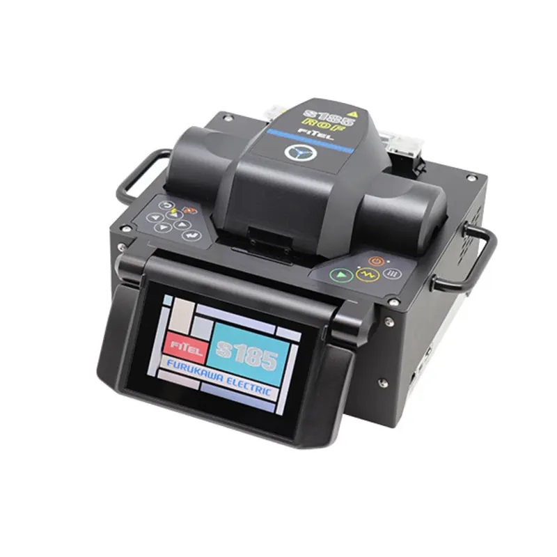
S185ROF
|
S185PMROF
|
| Heat Source For Splicing |
ROF (Ring of Fire, Three electrodes Arc-discharging) |
ROF (Ring of Fire, Three electrodes Arc-discharging) |
| Applicable Fibers*¹ |
SM, MM, DS, NZDS, High-Index, EDF, LDF |
SM, MM, DS, NZDS, High-Index, EDF, LDF, PMF |
| Cladding Diameter |
125 to 800 μm |
125 to 800 μm |
| Coating Diameter |
160 to 2000 μm (In Fiber holder)
160 to 900 μm (Coating clamp splice)
|
160 to 1300 μm (In Fiber holder)
160 to 900 μm (Coating clamp splice)
|
| Fiber Cleave Length |
6 mm*² (Coating clamp splice)
8 – 11 mm (Cladding clamp splice)
|
6 mm*² (Coating clamp splice)
8 – 11 mm (Cladding clamp splice)
|
| Typical Splice Loss*² |
SM (ITU-T G652): 0.014 dB |
SM (ITU-T G652): 0.014 dB |
| Typical Extinction Ratio*² |
– |
PANDA: 40 dB*⁴ (Angle offset: 0.6 degree) |
| Return Loss |
>60dB |
>60dB |
| Typical Splice Time*⁴ |
15s (SM by cladding clamp splice) |
15s (SM by cladding clamp splice)
50s (PANDA by cladding clamp splice) |
| Tension Strength |
1.96 (+0% to +20%) |
1.96 (+0% to +20%) |
| Applicable Protection Sleeve Length |
10 to 60 mm |
10 to 60 mm |
| Typical Heat Time |
35s (S922: 40 mm sleeve) |
35s (S922: 40 mm sleeve) |
| Splice Programs |
Max. 200 |
Max. 200 |
| Heater Programs |
Max. 100 |
Max. 100 |
| Splice Data Storage |
Max. 1000 including 4 images before and after splice |
Max. 1000 including 4 images before and after splice |
| Fiber Image Magnification on LCD |
104X, 278X or 556X |
104X, 278X or 556X |
| Dimension |
210W X 180D X 150H mm |
210W X 180D X 150H mm |
| Weight (without Battery) |
4.55 kg |
4.8kg |
| Monitor |
4.3" wide color LCD with touch panel |
4.3" wide color LCD with touch panel |
| Data Output |
USB ver. 2.0 type A: 1 port
USB ver. 2.0 mini B: 1 port
|
USB ver. 2.0 type A: 1 port
USB ver. 2.0 mini B: 1 port
|
| Operating Temperature |
0 to 40 °C |
0 to 40 °C |
| Storage Temperature |
-40 to 60 °C |
-40 to 60 °C |
| Humidity |
0 to 90% (Non-condensing) |
0 to 90% (Non-condensing) |
| Power Source |
AC input 100 to 240V (50/60Hz) |
AC input 100 to 240V (50/60Hz) |
| Notes |
*1 Fibers should be applied to ITU-T standard. In case of other fibers, depending on the type of fiber, the optimization of splice program may be needed or the splice result may not be satisfied.
*2 Due to the high temperature of ROF, it may not be possible depending on the diameter, thickness and material of the coating.
*3 These are references. Depending on the environment and condition, the number vary.
*4 Extinction ratio 40dB is measured in the condition that the initial extinction ratio is more than 50dB and there is the splice with 0.6 degree of rotation offset.
*5 This value is references. Depending on the type of fiber and condition of fiber on splicer, the number can vary.
|