Optimized for Aerial- and Duct Installation with fiber counts up to 96 fibers


All-Dielectric, Self Supporting (ADSS) Aerial Loose Tube Fiber Optic Cable Dry core design PowerGuide® SkyLight
All-Dielectric, Self Supporting (ADSS) Aerial Loose Tube Fiber Optic Cable Dry core design PowerGuide® SkyLight
Optimized for Aerial- and Duct Installation with fiber counts up to 96 fibers
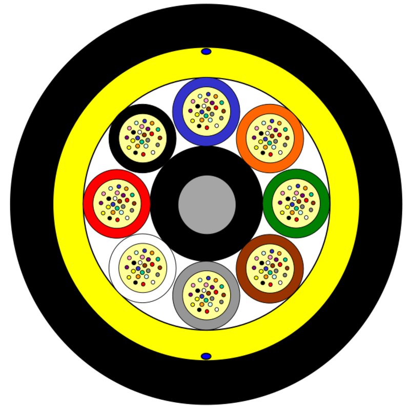
Version illustrated is the 96 Fiber 8 Element Cable
| Product Specification | |||||
|---|---|---|---|---|---|
| Fiber Count | Tubes | Core Design | Outer Diameter [mm] | Cable Weight [kg/km] | AT-Code** |
| 84 | 7 (12F) | 1+8 (1 Filler*) | 11.9 | 120 | AT-[][][]17UT-084-CMEA |
| 96 | 8 (12F) | 1+8 | 11.9 | 120 | AT-[][][]17UT-096-CMEA |
| This table shows nominal diameter and weight values which may differ in shipments. *Fillers are natural colored. **Please refer to the LIGHTERA AT- Code. The blanks specify the fiber type. |
|||||
| Identification Tube and Fiber Color Code | |
|---|---|
| 1 | Blue |
| 2 | Orange |
| 3 | Green |
| 4 | Brown |
| 5 | Grey |
| 6 | White |
| 7 | Red |
| 8 | Black |
| 9 | Yellow |
| 10 | Violet |
| 11 | Pink |
| 12 | Aqua |
| Note | Alternative tube and fiber color code available on request. |
| Sheath Marking |
|---|
| Lightera OPTICAL ADSS CABLE [ID] [MM/YYYY] [Handset Sign] xxxF [Meter Marking] Alternative sheath printing available on request. In case of order the exact sheath printing text will be clarified with the customer. |
| Shipping Information | |||
|---|---|---|---|
| Cable Length | Drum Diameter | Drum Width | Shipping Weight (calc.) Cable + Drum |
| 2 Km | 1200 mm | 780 mm | 310 kg |
| 4 Km | 1400 mm | 780 mm | 570 kg |
| 6 Km | 1550 mm | 1060 mm | 850 kg |
| 8 Km | 1700 mm | 1060 mm | 1130 kg |
| The shipping information are given for one-way reels. Reusable reels are available on request. | |||
| Temperatures (IEC 60794-1-22-F1) | |
|---|---|
| Operation | -40°C to +70°C |
| Installation | -15°C to +60°C |
| Storage/shipping | -40°C to +70°C |
| Standard | IEC 60794-1-22-F1 |
| Sag and Tension Calculation AT-[ ][ ][ ]17UT-xxx-CMEA | |||
|---|---|---|---|
| Conditions | NESC Light Loading | NESC Medium Loading | NESC Heavy Loading |
| Ice Thickness | 0 mm | 6.4 mm | 12.7 mm |
| Wind Pressure | 431 N/m² (95.5 km/h) | 192 N/m² (63.6 km/h) | 192 N/m² (63.6 km/h) |
| Low Temperature | -1 °C | -9.4 °C | -17.8 °C |
| Safety Factor | 0.73 N/m | 2.92 N/m | 4.38 N/m |
| Tension @ Maximum Span for 1,0 % Installation Sag |
|||
| Maximum Span | 150 m | 100 m | 60 m |
| MRCL (Maximum Rated Cable Load) | 4000 N | 4000 N | 4000 N |
| MIT (Maximum Installation Tension) | 2100 N | 1400 N | 850 N |
| Installation Temperature | 23 °C | 23 °C | 23 °C |
| Cable Modulus | 798.2 kg/mm² | 798.2 kg/mm² | 798.2 kg/mm² |
| CTE (C-1) | 1.67E- 05 | 1.67E- 05 | 1.67E- 05 |
|
|---|
| PLP: | |
| Dead End Assembly: |
FIBERLIGN® Dielectric Dead-end for ADSS, 2872003C1E1, Max. Tension: 2500 lbs. (1135 kg) |
| Fixed Tangent Support: |
FIBERLIGN® Aluminum Support for ADSS, 4450099 |
| Suspended Support: |
FIBERLIGN® Aluminum Suspension for ADSS, 4450199 |
| Slack Storage Devices: |
FIBERLIGN® In-Span Storage System, FIS12A |
| Down Lead Cushion: |
FIBERLIGN® Downlead Cushion for ADSS, 8003041 |
| Vibration Dampers: |
FIBERLIGN® Dielectric Damper for ADSS Cable, 50502272 |
| Telenco: |
|
| Dead End Assembly: |
TELENCO® GSDE AR Helical dead-ends with armor rods, Model GSDE AR 1150 (PN 7641) |
| Vibration Dampers: |
TELENCO® Vibration damper VIB, Model VIB117 (PN 09140) |
| Suspension Support: |
TELENCO® DSAL Mobile suspension clamp, Model DSAL1150 (PN 09568) |
| Pertinent Installation Information | |
|---|---|
| Maximum Rated Cable Load (MRCL) | 4.0 kN |
| Bending Performance (IEC 60794-1-21-E11): | |
| Handling Fixed Installed | No attenuation increase (Bend radius: 120 mm) |
| During Installation (Under Load): |
No changes in attenuation before versus after load (Bend radius: 240 mm) |
| Note | *No changes in attenuation means that any changes in measurement value, either positive or negative within the uncertainty of measurement shall be ignored. The total uncertainty of measurement shall be less than or equal to 0.05 dB. |
| When to Use Hardware |
|
|---|---|
| Dead End Assembly: • Used whenever a cable should not slip:
|
|
| Tangent and Suspension Supports: • Typically used in small line angle (<20°, depending on type) • Provides vertical support, not designed to support cable tension • Multiple types depending span length and application • Allows cable slippage during imbalanced load situations |
|
| Vibration Dampers: • ADSS cables can experience Aeolian vibration under certain circumstances • Circumstances conducive to Aeolian vibration • Laminar wind flow, Wide open spaces, Light winds, High tensions • Vibration dampers minimize the effects of this vibration |
| Installation Document References |
|---|
| IP 014 PowerGuide® Installation IP 014A PowerGuide® ADSS CABLE Installation Guideline Distribution Line Applications IP 006 PowerGuide® Sheath Removal IP 017 PowerGuide® Hardware Installation AN-101 Maximum Rated Cable Loads & Minimum Bending Diameter AN-203 Space Potential Calculation for PowerGuide® ADSS Cable |
Installation documents available upon request
| PowerGuide SkyLight Cable Ordering Information | |||
|---|---|---|---|
| Example | AT-3BE17UT-NNN¹-CMEA |
||
| Part Number | Fiber² Sheath Core Fiber Count Custom³ AT-S1 S2 SF S3 S4 S5 S6 NNN – CMEA |
||
| S1 | Fiber Selection: 3= 1310/1550 nm (AllWave® ZWP Fiber) 1310/1550 nm (AllWave® + ZWP Fiber) 5= 1310/1550 nm (AllWave®FLEX ZWP Fiber) 7= 1310/1550 nm (AllWave®FLEX + ZWP Fiber) |
||
| S2 | Fiber Transmission Performance: B= 0.35/0.31/0.27/0.25/0.27 dB/km @ 1310/1385/1490/1550/1625 nm (AllWave® ZWP Fiber) E= 0.36/0.31/0.27/0.25/0.27 dB/km @ 1310/1385/1490/1550/1625 nm (AllWave®FLEX ZWP Fiber) (AllWave®FLEX + ZWP Fiber) C= 0.35/0.31/0.27/0.25/0.27 dB/km @ 1310/1385/1490/1550/1625 nm (AllWave® + ZWP Fiber) |
||
| SF | Fiber Type: E= AllWave® ZWP Single Mode | ||
| S3 | Sheath Construction: 1 = All-Dielectric single jacket | ||
| S4 | Tensile Load: 7 = ADSS | ||
| S5 | Core Type U = Dry Core Loose Tube | ||
| S6 | Fibers per Tube: 6 = Fibers 8 = Fibers N = 10 Fibers T = 12 Fibers |
||
| NNN | Fiber Count |
||
| Note | ¹ Part Number shown is for PowerGuide ADSS Cable with 250 µm Single Mode AllWave ZWP Fibers with maximum attenuation: 0.35/0.31/0.27/0.25/0.27 dB/km @ 1310/1385/1490/1550/1625nm ² Contact LIGHTERA sales representative for information on other cable variations, including additional fiber types, composite cables and attenuation. ³ Consult with us regarding your application, span lengths and loading conditions to complete the custom design and part number of your complete sheath strengths system. |
||
The information is believed to be accurate at time of issue.
Lightera reserves the right to make changes to the product(s) described in this document at any time without notice. This document is for informational purposes only and is not intended to modify or supplement any Lightera warranties or specifications relating to any of its products or services.
For additional information please contact your sales representative.
You can also visit our website at lightera.com or email cableinfo@lightera.com

Compare features, sizes, models to find the perfect option for you