
Part no -
07525-01
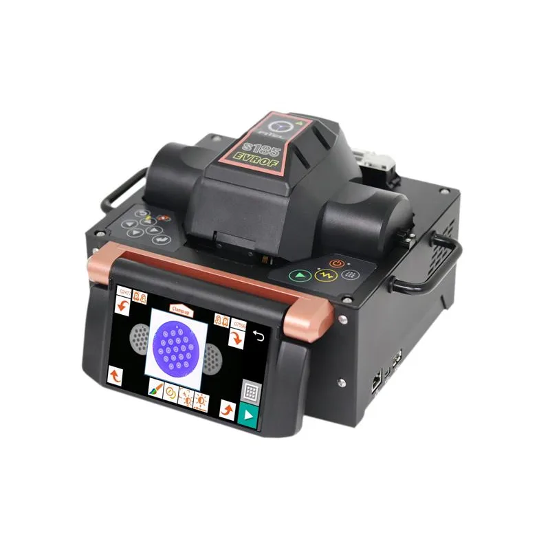
S185EVROF/S185EDV
The FITEL S185EVROF combines the cutting-edge features of ROF (Ring of Fire) and EDV (End View) into a single, unprecedented device. The End View System enhances user control, by offering detailed images of fiber cross-sections, making it particularly effective for intricate internal structures such as multi-core and hollow-core fibers.
The FITEL S185EVROF combines the cutting-edge features of ROF (Ring of Fire) and EDV (End View) into a single, unprecedented device. The End View System enhances user control, by offering detailed images of fiber cross-sections, making it particularly effective for intricate internal structures such as multi-core and hollow-core fibers.
Image
Features And Benefits
| S185EVROF | S185EDV |
| Three electrode Ring of FireTM arc-discharging and STA2DTM | Tailored for fiber with complex internal structure |
| Dual Mirror System-simultaneous view of both fiber ends | Dual Mirror System-simultaneous view of both fiber ends |
| World’s first Composite Image Technology – both fiber images overlapped for precise alignment | World’s first Composite Image Technology – both fiber images overlapped for precise alignment |
| Best-in-class, compact and portable solution for hollow-core and multi-core fibers | Compact, lightweight and portable |
| STA2D – sequential asymmetric arc-discharge fine tuned for all types of hollow-core fiber and small cladding fibers | Highly accurate rotational alignment (0.1 degree) |
| Composite Image Technology overlays both end view fiber images into one picture ensuring precise match | Adjustable front & rear LEDs for sharper fiber Image |
| Highly accurate rotational alignment (0.1 degree) | Alignment assistance using color filters |
| Side view mode for traditional fibers | Side view mode for traditional fibers |
Product Description
The FITEL S185EVROF combines the cutting-edge features of ROF (Ring of Fire) and EDV (End View) into a single, unprecedented device. The End View System enhances user control, by offering detailed images of fiber cross-sections, making it particularly effective for intricate internal structures such as multi-core and hollow-core fibers.
The proven three-electrode arc discharge system, known for achieving low loss on multi-core fibers, is now reinforced by allowing end-users to view fiber cross-sections before splicing. HCF and MCF are especially sensitive fibers, with excessive heat potentially compromising their structure. The three-electrode discharge ensures uniform heating, while our STA2 D (Sequential Triangular Asymmetric Arc Discharging) system effectively heats the delicate structure of hollow-core fibers, preserving the internal microstructure.
Integrating these three systems results in precision splicing performance and industry-leading low loss.
The S185EDV employs an End View system designed for splicing fiber with complicated internal structure such as Hollow Core, PCF and more. These fibers can be very difficult to align using a traditional Side View splicer.
Viewing the cross sections images of the fibers gives more detail about the internal structure providing more control to the user for precise splicing results.
Our Composite Image Technology overlays both End View fiber images into one picture, allowing the user to verify the alignment and fine tune to their exact requirements. The S185EDV can also be used to splice in traditional Side- View mode. All these features make the S185EDV a versatile, portable and precise splicing solution.
Specification
| Specification | |||||
|---|---|---|---|---|---|
| Description | S185EVROF | S185EDV | |||
| Applicable Fibers*¹ | SM, MM, DS, NZDS, High-Index, EDF, LDF, PMF, MCF, HCF | SM, MM, DS, NZDS, High-Index, EDF, LDF, PMF, MCF | |||
| Cladding Diameter | Splice: 80*2 to 800 μm End view: 125 to 500 μm |
125 to 500 μm | |||
| Coating Diameter | 160 to 1300 μm (In Fiber holder) 160 to 900 μm (Coating clamp splice) |
||||
| Fiber Cleave Length | 3 mm (Coating clamp splice) 8 to 10 mm (Cladding clamp splice) |
3 to 4 mm (Coating clamp splice) 8 to 10 mm (Cladding clamp splice) |
|||
| Typical Splice Loss*3 | SM (ITU-T G652): 0.014 dB | ||||
| Typical Extinction Ratio*3 | PANDA: 40 dB*4 (Angle offset: 0.6 degree) | ||||
| Return Loss | >60 dB | ||||
| Typical Splice Time*5 | 15 s (SM by cladding clamp splice) 50 s (PANDA by cladding clamp splice) |
||||
| Tension Strength | 1.96 N (+0% to +20%) | ||||
| Applicable Protection Sleeve Length | 10 to 60 mm | ||||
| Typical Heat Time | 35s (S922:40 mm sleeve) | ||||
| Splice Programs | Max.200 | ||||
| Heater Programs | Max.100 | ||||
| Splice Data Storage | Max. 1000 including 4 images before and after splice | ||||
| Fiber Image Magnification on LCD | 104 X, 278 X or 556 X (Side view) 64 X (End view) |
||||
| Dimension | 210 W x 180 D x 165 H mm | ||||
| Weight (without Battery) | 4.9 kg | ||||
| Monitor | 4.3” wide color LCD with touch panel | ||||
| Data Output | USB ver. 2.0 type A: 1 port USB ver. 2.0 mini B: 1 port |
||||
| Battery capacity (Optional)*6 |
–
|
Typical 60 splice / heat cycles
|
|||
| Operating Temperature | 0 to 40 °C | ||||
| Storage Temperature | -40 to 60 °C | ||||
| Humidity | 0 to 90% (Non-condensing) | ||||
| Power Source | AC input 100 to 240V (50/60Hz) | ||||
| Note | *1 Fibers should be applied to ITU-T standard. In case of other fibers, depending on the type of fiber, the optimization of splice program may be needed or the splice result may not be satisfied. *2 Coating clamp splice (Coating Diameter >125 μm) *3 These are references. Depending on the environment and condition, the number vary. *4 Extinction ratio 40 dB is measured in the condition that the initial extinction ratio is more than 50 dB and there is the splice with 0.6 degree of rotation offset. *5 This value is references. Depending on the type of fiber and condition of fiber on splicer, the number can vary. *6 This value can produce using fully charged brand new battery at room temperature 20 degree C. Depending on the condition of the battery and operation environment, the number can vary. |
||||
Standard package
| Standard Package | |||||||
|---|---|---|---|---|---|---|---|
| Item | P/N | Quantity S185EVROF -00 | Quantity S185EVROF -01 |
Quantity S185EDV -00 |
Quantity S185EDV -01 |
Quantity S185EDV -10 |
Quantity S185EDV -11 |
| S185EVROF Main body | S185EVROF-X-A-0001 | 1 | 1 | – | – | – | – |
| S185EDV Main body |
S185EDV-X-A-0001 | – | – | 1 | 1 | 1 | 1 |
| Hard Carrying Case | HCC-12 | – | 1 | – | 1 | – | 1 |
| Built-in Battery Pack | S947B | – | – | – | – | 1 | 1 |
| AC Adapter | S185EVROF: MDS-150AAS24BD S185EDV: S981A |
1 | 1 | 1 | 1 | 1 | 1 |
| AC Cable Code | – | 1 | 1 | – | – | – | – |
| AC Cable Cord | – | – | – | 1 | 1 | 1 | 1 |
| Z Stage Lock | ZL-01 | 1 pair | 1 pair | 1 pair | 1 pair | 1 pair | 1 pair |
| Spare Electrode | S185EVROF: ELR-07 S185EDV: ELR-03 |
1 set | 1 set | 1 pair | 1 pair | 1 pair | 1 pair |
| Change Tool for Vertical Electrode | – | 1 | 1 | – | – | – | – |
| Rear LED Cover for Small Diameter | – | 1 pair | 1 pair | 1 pair | 1 pair | 1 pair | 1 pair |
| Electrode Sharpener | D5111 | 1 | 1 | 1 | 1 | 1 | 1 |
| Cleaning Brush | VGC-01 | 1 | 1 | 1 | 1 | 1 | 1 |
| User Manual | – | 1 | 1 | 1 | 1 | 1 | 1 |
Optical Components
| Optical Components | |||
|---|---|---|---|
| Item | P/N | S185EVROF Quantity |
S185EDV Quantity |
| 160 μm Coating Fiber Holder | S713S-160 | 1 pair | 1 pair |
| 250 μm Coating Fiber Holder | S713S-250 | 1 pair | 1 pair |
| 300 μm Coating Fiber Holder | S713S-300 | 1 pair | 1 pair |
| 400 μm Coating Fiber Holder | S713S-400 | 1 pair | 1 pair |
| 500 μm Coating Fiber Holder | S713S-500 | 1 pair | 1 pair |
| 550 μm Coating Fiber Holder | S713S-550 | 1 pair | 1 pair |
| 650 μm Coating Fiber Holder | S713S-650 | 1 pair | 1 pair |
| 900 μm Coating Fiber Holder | S713S-900 | 1 pair | 1 pair |
| 1300 μm Coating Fiber Holder | S713S-1300 | 1 pair | 1 pair |
| 550 μm Coating BW Fiber Holder | S713B-550 | 1 pair | 1 pair |
| 1000 μm Coating BW Fiber Holder | S713B-1000 | 1 pair | 1 pair |
| Fiber Holder for Loose Tube | S713S-250LT | 1 pair | 1 pair |
| Customized Fiber Holder*1 | S713S-XXX | 1 pair | 1 pair |
| USB Cable | USB-01 | 1 | 1 |
| Wi-Fi Dongle | WFD-01 | 1 | 1 |
| *1 Available Suitable size Fiber holder depending on the coating diameter of splicing fiber. | |||
Export Control Regulations
The products and/or technical information presented in this publication may be subject to the application of the Foreign Exchange and Foreign Trade Act and other related laws and regulations in Japan. In addition, the Export Administration Regulations (EAR) of the United States may be applicable.
In cases where exporting or reexporting the products and/or technical information presented in this publication, customers are responsible for following the necessary procedures at their own risk and expense. Please contact the Ministry of Economy, Trade and Industry of Japan or the Department of Commerce of the United States for details about procedures.
Contact Information
For additional information please contact your sales representative. You can also visit our website at www.lightera.com or call 1-888-FIBERHELP (1-888-342-3743) USA or 1-770-798-5555 outside the USA. For a full list of our certifications, visit our website.
Trademark Notice and Disclaimer
Lightera reserves the right to make changes to the product(s) described in this document at any time without notice. This document is for informational purposes only and is not intended to modify or supplement any Lightera warranties or specifications relating to any of its products or services.
Compare products and choose the best one
Compare features, sizes, models to find the perfect option for you
